Wednesday, March 19, 2014

Grade Compensation for the Horizontal Curves on Highways

Hi,

Grade or Gradient is  the ratio of vertical rise or fall of the road center line with respect to its length. It has to be provided for the vertical alignment of the road. 

When we provide gradient to the road, vehicle has to apply more power to overcome the component of the gravity force. Higher the grade/slope,  larger is the effort required.


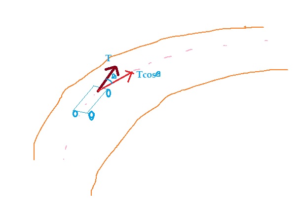
In a horizontal curve the effective tractive effort of the vehicle is reduced because of the turning angle. 

Suppose 'T' is the tractive effort of the vehicle, and the turning angle of the front wheel is 'theta' then the tractive effort in that direction will be less.

There will be a loss of tractive effort equal to (T-T.cos.theta). This loss in the tractive effort has to be compensated at the horizontal curves which also have the vertical grade. It is done by reducing the grade, this is known as the grade compensation.

According to IRC, a grade compensation  of,  (30+R/R), maximum 75/R  has to be provided for the grades more than 4%.
No grade compensation is required for the lower values of the the grade.
Here, R is the radius of the horizontal curve in meters.

Thanks for your kind visit!


Monday, March 17, 2014

Steps for Construction of Earth roads

Hi, 
today I am going to share with you the steps which are necessary for the construction of the earth roads. 


  • General :
First of all what is an earth road? Earth road is a type of road whose whole pavement section is constructed with the locally available earth material preferably. Borrow pits are located at the nearby sites preferably outside the land width  where, the required earth is available.

Sub-grade and the surface of the earth roads are given larger camber of 1in 33 to 1 in 20 because they need faster drainage to be safe from the moisture. A maximum value of camber of 1 in 20 is the limit because higher camber will result in the formation of cross ruts and corrosion of pavement soils.


  • Specifications of Materials:
The earth material used for the construction of earth roads are termed as satisfactory if they possess the following properties:
                                               Base Course                         Wearing Course


  1. Clay content                       <5%                                      10 to 18%
  2. Silt content                       9 to 32%                                  5 to 15%
  3. Sand content                     60 to 80%                               65 to 80%
  4. Liquid limit                          <35%                                      <35%
  5. Plasticity Index                     <6%                                      4 to 10%
  • Construction steps(Procedure):
Material: 
Suitable borrow pits are located by doing the survey of the adjacent land which are easy to reach and at economical haulage distance. The various organic materials like trees, shrubs and grass roots are removed before the excavation of the earth.

Location of the centerline: 
The centerline and the road boundaries are marked on the ground by driving the wooden pegs. 

To follow the desired vertical profile of the road, reference pegs are also driven at a certain spacing which depends upon the estimated length of the road construction per day.

Preparation of the subgrade: Following steps are necessary for the preparation of the sub-grade:  (a) Clearing site 
(b) Excavation and construction of fills
(c) Shaping of sub-grade.
The site clearance may be done manually using appliances like spade, pick and hand shovel or using the mechanical equipment like Bulldozer and scraper etc.
Excavation and construction of fills may also be done manually or using the excavation, hauling and compaction equipment.  Dozers are considered very useful for haulage of short distances. 

If the compaction is done manually it will not be sufficient and proper, it should be left to get consolidated under atmospheric conditions. 

Various equipment used by manual labor are shovel, spade, pick-axe, baskets, rammers and hand rollers.                                                        The subgrade should be compacted to the desired grade, camber and longitudinal profile.

Pavement construction: 
The soil is dumped on the prepared sub-grade and pulverized. The soil may be a mixture of more than one soil to get the desired properties. The moisture content is checked and if extra moisture is needed, is added to bring it to OMC.
The soil is mixed, spread and rolled in layers such that the compaction thickness of each layer does not exceed 10 cm. 

The type of roller for compaction is decided based on soil type, desired amount of compaction and availability of equipment. At Least 95% of dry density of I.S. light compaction is considered desirable. The camber of the finished surface is checked and corrected when necessary.

Opening to traffic: The compacted earth surface is allowed to dry out for few days and then is opened to traffic.
Thanks for your kind visit!


Thursday, March 13, 2014

Highway Compaction Equipment

Hi,
 There are various types of compaction equipment:


  1. Rollers
  2. Rammer
  3. Vibrators
a. Rollers: Rollers are vastly used in the highway construction for compacting the subgrade and other layers. They are again of three types:
Smooth wheeled roller (Image source:Google images)
  1. Smooth wheeled rollers:  These are used for compacting granular soils and specially useful where crushing is required. Smooth wheeled rollers generally vary from 4 to 22 tonnes in their weight. 
b. Pneumatic Tyre rollers: These are used for compacting the silty and sandy soils and not preferred for clayey and granular soils.


    Pneumatic Tyre roller ( Image source: Google images)


 c. Sheep's foot rollers: These rollers are having hollow cylindrical wheels having sheep's foot shaped projections on their surfaces. 

They are suitable for compacting the clayey soils, specifically where needing action is required and along with them smooth wheeled rollers may be used for giving a smooth surfacing to top surface.
2. Rammers: Rammers are used where rollers are not suitable due to the area constraints. They are mechanically operated using the electric energy.


3.Vibrators:
Vibrators are suitable for compaction of the sandy soils and specifically cohesion-less soils. They can also be used along the rollers in their dual combination.


Vibrators (Image source: Google Images)
Thanks for you visit!

Highway Excavation Equipment

Hi, 
how you doing? Today I am going to post here what I learnt about the highway construction equipment.

As we know that highway construction at field can be broadly classified into two phases:


  1.  Excavation or preparation of sub-grade.
  2. Pavement layers construction.
In the phase of the excavation or preparation of the sub-grade we need two types of equipment:
  1. Excavation equipment
  2. Compaction equipment
In this post I will discuss the excavation equipment. Types of excavation equipment that is to be used depends upon the type of the soil and availability of the equipment. Various equipment used in general for the excavation of the sub-grade are
  1. Bull Dosser
  2. Scraper
  3. Power Shovel
  4. Drag-line
  5. Clam-shells
  6. Hoe
  • Bulldozer 
Bulldozer is a crawler equipment used to push and haul the earth material up a distance of 100 m using its front blade and a ripper attached at its rear.
Bulldozer (source: wikipedia)

 Bulldozer is a versatile equipment because it can be used in undulating ground or level ground, can be used for various building construction projects including pilot road constructions or even in farms.
  • Scraper: Scraper is having a blade in its rear part which is used to scrap the earth and then to store it in the bowl. Once the bowl is full the loose earth can be hauled to the deposition site. There is an elevator arrangement for the blade which can elevate or lower the blade according to the need.
  • Scrapper (Source: Google images)
  • Power Shovel: Power shovel is a power equipment used to dig the earth material at lower depths than the standing elevation. The parts of a power shovel are crawler mounting, cab, boom, shovel and hoist cable.
    Power Shovel (image Source: wikipedia)
    Power shovel can be used to excavate the loose earth material effectively and can  be used in undulating grounds because it has a crawler mounting.
  • Drag-Line: Drag line has a bucket suspended from the book which can be dragged with a drag cable and hoist cable to collect the loose material inside the bucket. 
    Drag Line (Image source: wikipedia)
    Image shown above shows a drag-line with all its major parts. Drag line can be used to collect the loose material from a much larger depths.
  • Clam-shell :
Clam-shell bucket is combination of two shells which are joined together with hinges at top and when these half are closed form a bucket. It is attached to a cable and a boom arrangement and to lift the material it is made to fall on it and then lifted up. In the lifting operation clam-shells close them up and will lift the material filled inside.
Clam-shell

  • Hoe: Hoe can be used to excavate relatively stiffer earth from a depth below the standing level of the equipment. This material can excavate all types of earth materials except hard rocks.

Thanks for your kind visit!


Wednesday, March 5, 2014

Design of Dowel bars - Rigid Pavements.

Hi,
How you doing? Let's discuss the design of the dowel bars. So, what are dowel bars first?

  • Dowel bars

 Dowel bars are steel bars, generally round in shape,  and are used in the expansion joints which, are provided in the concrete pavements(rigid pavements) to allow the expansion of the concrete slab.
The main function of the dowel bars is to transfer the wheel load from one slab to the adjacent slab through the shear and bending moment.

Dowel bars are embedded on both the slabs, and on one slab there is a dowel cap which provides space for the bar to occupy it when there is expansion in both slabs.
This empty space is filled with some easy to contract material so, that it may adjust its volume according the need of the dowel bar.

Design of Dowel bars:
In order to design the length and diameter of the dowel bar we have to check its failure under the action of wheel load on the pavement slab.
Failure may occur in three ways:

  1. Failure of the dowel in shear
  2. Failure of dowel bar in flexure
  3. Failure of concrete in bearing.
Steps:
  1. According to Indian roads congress(IRC) the following formulas(given in image) are used to find the load capacity of the dowel under shear, flexure and that of concrete in bearing. Three formula are given in the image below.
    Dowel bars- design formula (Courtesy: Highway Engg. By S.K. Khanna and C.E.G.Justo)
  2. Generally the thickness of the expansion joint and diameter of the dowel bars are fixed.  We first find out the length of the bar by equating the second formula with the third formula assuming that the load capacity of the concrete in bearing is equal to the flexure capacity of the dowel bar. The formula is given below in image, length has to be found by trial and error method.
    Length of Dowel bar ( Source: Highway Engg. by S.K.Khanna & C.E.G. Justo)
  3. Then use that length to find out the three load capacities corresponding the these three formulas. The lesser of the three will be the capacity of the dowel bar because, failure at any case is the failure of the pavement system.
It is assumed that the wheel load is transferred to a distance of 1.8.l from the application of the load. The capacity factor of the dowel system is defined as the ratio of the load capacity of the dowel system to the load capacity of the single dowel bar.
We must check the dowel system to be sufficient to provide the corresponding load factor and that will decide the spacing of the dowel bars and therefor the numbers of dowels required.

Thanks for your visit!


Tuesday, March 4, 2014

Bitumen Penetration Test to Find out its Grading.

Hi,

We know that penetration test is one of the important tests, which is performed to test the grade of the Bitumen. You might be looking this article to jot down the theory and procedure of the test into your laboratory/practical notebook or might be checking just to refresh your knowledge. If you have one of these reasons, reading this article surely is going to help you in fulfilling the purpose. So, here we go:

AIM: 

To find out the consistency/hardness of the Bitumen and thereby to find out its grade using the Bitumen penetration test.

APPARATUS: 


  1. Standard Penetration test apparatus with all the accessories such as, needle, weight and timer.
  2. Heater
  3. water bath with temperature control, maintained at 25° ± 0.1 °C, containing not less than 10 litres of water.
Accessories to the Standard penetration test are:

  • Container: flat bottomed cylindrical metallic dish having 55 mm diameter and 35 mm depth.
  • Penetration Needle: A straight, highly polished cylindrical hard steel rod having a diameter of about 1 mm.
  • Time measuring device with an accuracy of 1 second.


THEORY:

 This test is used to check the grade of the bitumen. In other words, it is used to check the consistency or the hardness of the bitumen which is useful to find out the suitability of the bitumen to use under different climatic conditions.
Penetration value is a measure of hardness or consistency of bituminous material. It is the vertical distance traversed or penetrated by the point of a standard needle in to the bituminous material under specific conditions of load, time and temperature. 
This distance is measured in one tenths of a millimeter so, if the reading is 50 mm, that denotes a penetration of 5 mm. This test is used for evaluating consistency of bitumen. It is not regarded as suitable for use in connection with the testing of road tar because of the high surface tension exhibited by these materials.


PROCEDURE:

  1. Preparation of sample: Soften the material to a pouring consistency at a temperature not more than 60°C for tars and 90°C for bitumen above the approximate softening point and stir it thoroughly until it is homogeneous and is free from air bubbles and water. Pour the melt into the container to a depth at least 10mm in excess of the expected penetration. Protect the sample from dust and allow it to cool in an atmosphere at a temperature between 15° to 30° C for one hour. Then place it along with the transfer dish in the water bath at 25° ± 0.1 °C, unless otherwise stated.
  2. Put the test cup upon the stand of the penetration apparatus.
  3. Clean the needle with benzene, dry it and load with the weight. The total moving load as per standards, must be 100 ± 0.25 gms, including the weight of the needle, carrier and super-imposed weights.
  4. Adjust the needle to make contact with the surface of the sample. This may be done by placing the needle point in contact with its image reflected by the surface of the bituminous material.
  5. Make the pointer of the dial to read zero or note the initial dial reading.
  6. Release the needle for exactly five seconds for which you can use the timer or stopwatch if timer is not provided with the apparatus.
  7. Adjust the penetration machine to measure the distance penetrated.
  8. Make at least 3 readings at points on the surface of the sample not less than 10 mm apart and not less than 10 mm from the side of the dish. 
  9. After each test return the sample and transfer dish to the water bath and wash the needle clean with benzene and dry it. In case of material of penetration greater than 225, three determinations on each of the two identical test specimens using a separate needle for each determination should be made, leaving the needle in the sample on completion of each determination to avoid disturbance of the specimen.


PRECAUTIONS:

  • Remember that sample must be tested at 25 degrees Celsius so, sample must be prepared with the standard procedure listed above.
  • There should be no movement of the container while needle penetrates into sample.
  • The needle should be cleaned with benzene and dried before penetration.


OBSERVATIONS
Actual test temperature = °C
 Penetration dial readingTest 1Test 2Test 3
(i)Initial
(ii)Final
Penetration Value=
Mean = 
RESULT:
Mean Penetration Value =
Thank you for visiting, visit again!

Friday, February 28, 2014

Critical Stress Combination for Rigid Pavements

Hi, How you doing?
As we know that the design of a pavement is governed by the analysis so, this is very important to know the various combinations of stresses that will be induced in the slab. There are two kinds of loading:

  1. Traffic Loading
  2. Temperature variation.
Traffic loading will induce the compressive or tensile stresses in the pavement and temperature variation results in to kinds of stresses. One is known as warping stress and another is frictional stress.

That makes total of three kinds of stresses that will be induced in the pavement slab. Now, we have to find out the critical combination of these three.

  • In Summer Season:
In summer season the average temperature is higher and it results in the overall expansion of the slab. This induces the frictional stresses which will be compressive so as to restrict the expansion. Remember friction will always act in the opposite direction of the movement of the bottom of the slab. That means when it tries to expand, friction will try to contract it or restrict the expansion. That makes it to induce the compressive stress.

In the after mid-noon hours in summer season, the temperature at the top layer will be higher as compare to the bottom layer. That will make the slab to tend to warp in downward direction. Under the self weight of the slab warping will be restricted and therefore will result in the tensile stress in the bottom layer.

 Downward warping results in contraction of the bottom layer which is restricted through the induction of the tensile warping stress. So, warping stress of tensile nature is induced.
Now, at the edge region the traffic load stress of tensile nature is also induced and that is where the critical load combination is formed.

Critical stress combination(At the edge)  = Traffic stress + Warping stress - frictional stress.


  • In Winter Season:
In the after mid-noon hours in winter season again, traffic load stress and the warping stresses will be tensile in the bottom layer. Also, the frictional stresses will be tensile because, there is overall contraction of the pavement due to lower average temperature and therefore friction will act along the tensile direction.
So, the Critical stress combination(At the edge)  = Traffic stress + Warping stress + frictional stress.

At the corners the critical load combination is that of the traffic load and the warping stress at the top layer at the mid-night hours.
See, in the night the temperature at the bottom layers will be higher as compare to the temperature at the top layers so, there will be upward warping. That will induce tensile warping stress at the top layer.
 So, Critical stress combination(At the corner)  = Traffic stress + Warping stress 

Thank you for your time!

Sanjay.


Cut and Fill Volume for given GL and FL profile, using Python Code

Hi, Please don't get afraid by the length of the code. It is very simple to copy and paste it into your Python IDEs such as Pycharm or V...